Research Facility
Climatic chamber

TOKYO POLYTECHNIC UNIVERSITY
The School of Architecture & Wind Engineering
Global COE program secretariat 1583, Iiyama, Atsugi-shi, Kanagawa, 243-0297, Japan
TEL & FAX:046-242-9658
E-mail:gcoeoffice@arch.t-kougei.ac.jp
|
|
|
A climatic chamber was constructed to systematically analyze the relationship between the natural crosswind fluctuations, the amount of sweat produced, and the skin temperature.
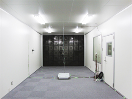
Figure 1 shows a plan view of the climatic chamber and Figure 2 shows the interior of the laboratory inside the climatic chamber. The climatic chamber was designed to meet the following air-conditioning requirements:
* Temperature: 20 to 35℃ ± 0.5℃
* Humidity: 40 to 70% ± 2%
* Wind velocity: 0.1 to 2.0 m/s
The climatic chamber has a dimension of 5 m wide × 11 m long × 3 m high. It houses a laboratory (3.7 m wide × 8 m long × 2.7 m high), a pre-room and a fan room.
The climatic chamber is equipped with:
* a heat source system consisting of a hot-water boiler and a brine chiller unit;
* two compact air-conditioning units (one with an air supply capacity of 3,000 m3/h and a cooling and heating capacity of 10.5 KW, and the other with an air supply capacity of 2,000 m3/h and a cooling and heating capacity of 7.0 KW); and
* an electrically-heated vaporizing humidifier (10.0 Kg/h).
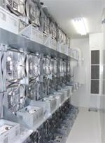
Figure 3 shows the airflow generator installed in the fan room. It is comprised of 48 plug fans driven by 280-W DC motors. It aims to reproduce the long-frequency fluctuations of the natural crosswind by controlling the revolution speeds of each motor from a desktop computer.
 |
|
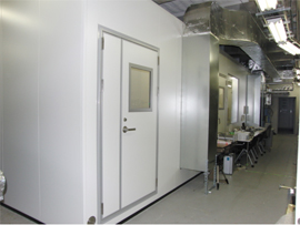 |
Figure 2. Interior of laboratory inside the climatic chamber |
|
|
| |
 |
|
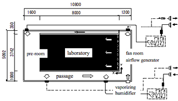 |
Figure 3. Fan room |
|
Figure 1. Plan view of the Climatic Chamber |
|
|
|